Due to the fact that a clutch is one of the major important components in a car, it is made of types to meet different requirements. In the previous lesson, the clutch is explained to be a mechanical device that engages and disengages the power transmission from the driving shaft to the driven shaft. We also revealed that it features two shafts, one is connected to the engine or power unit (the driving member) while the other shaft provides the power output that does the work.

Today we’ll be looking at the different types of clutch and their working principle.
Contents
Various types of clutch:
Below are the different types of clutch and how they work:
- Friction clutch
- Hydraulic clutch
- Centrifugal clutch
- Semi-centrifugal clutch
- Cone clutch
- Diaphragm clutch
- Electromagnetic clutch
- Dog and spline clutch
- Vacuum clutch
- Freewheel unit clutch
Let’s dive into their explanation!
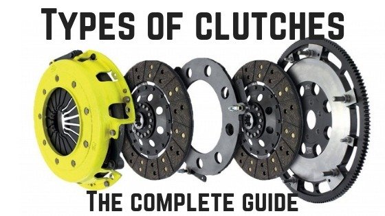
Friction Clutch:
The friction clutch is of two different types namely; single plate clutch and multiple plate clutch.
Single clutch plate: the single clutch is the most common and used clutch found on modern light vehicles. It helps to transmit torque/power from the engine to the transmission input shaft. It has just on the plate as the name has stated. This plate is attached to the splines of the clutch plate. The plate is a thin metallic disc which contains a friction surface on both sides.

Multiple clutch plate: just as the name states, a multiple clutch plate uses multiple clutches to make frictional contact with the engine’s flywheel. This transmits power between the engine shaft and the transmission shaft of the vehicle. The number of friction surfaces determines the capacity of the clutch to transmit torque. This clutch plate is fitted to the engine shaft and gearbox shaft. The multiple clutch works the same way as the single-plate clutch. It is achieved when the clutch pedal is pressed. The clutch is used in racing cars, heavy commercial vehicles and motorcycles for transmitting high torque.
The multiple clutch is of two types such as dry and wet; the clutch is said to be a wet clutch if it operates in an oil bath. It is a dry clutch if it operates without oil. The wet clutches are commonly used in connection with or as a part of the automatic transmission.
Hydraulic clutch:
The working principle of the hydraulic clutch is the same as the vacuum clutch. Their major difference is that the hydraulic clutch works with oil pressure whereas the vacuum clutch works with a vacuum. The major parts of this clutch system include an accumulator, valve control, pump, cylinder with piston and reservoir.
In the working principle of a hydraulic clutch, the oil reservoir pumps oil into the accumulator with the aid of a pump. This pump works together with the engine and the accumulator is connected to the cylinder through the control valve. The control valve is operated by the switch mounted on the gear lever. The piston is connected to the clutch by the linkage mechanism.
The switch opens the control valve when the driver holds the gear lever to change the gears, which allows the oil under pressure to the cylinder. The oil pressure moves the piston forward and backwards which causes the clutch to get disengaged. If the driver releases the gear lever the switch is open which closes the control valve and the clutch will be engaged.

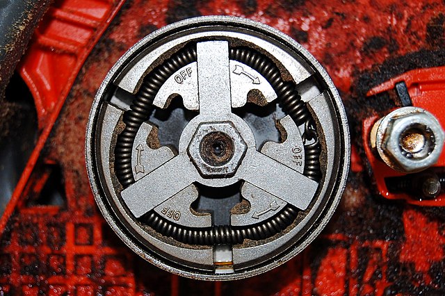
Centrifugal Clutch:
Centrifugal types of clutch use a centrifugal force to engage the clutch, unlike others that work with spring force. The clutch is automatically operated depending upon the engine speed which makes the elimination of the clutch pedal. The benefit of this clutch is that the driver easily stops the vehicle in any gear without stalling the engine. The vehicle can be easily started in any gear by pressing the accelerator pedal.
The working of a centrifugal clutch is quite different as it consists of weights A pivoted at B. The weights fly off due to the centrifugal force when the engine speed increases. The centrifugal force applied operates the bell crank levels which press plate C. The movement of plate C presses the spring E which extremely presses the clutch plate D on the flywheel against the spring G. This engages the clutch. The spring G helps to disengage the clutch at low speeds at about 500rpm and the stop H limits the movement of the weights.

Semi-centrifugal Clutch:
The semi-centrifugal clutch also uses centrifugal force along with a spring force which helps it in the engaged position. The clutch consists of levers, clutch springs, pressure plate, friction lining, flywheel and clutch plate. The levers and springs are arranged equally on the pressure plate. This spring is designed to transmit the torque at normal engine speed while the centrifugal force helps to transmit torque at higher engine speed.
The working of a semi-centrifugal clutch also occurs at normal engine speeds, when the power transmission is low the springs keep the clutch engaged. The weighted levers do not put any pressure on the pressure plate. And at high engine speed when the power transmission is high, the weights fly which allows the levers to exert pressure on the plate. This keeps the clutch firmly engaged. The springs in these types of clutches consist of less stiff springs which allows the driver not to experience any strain while operating the clutch.
Cone Clutch:
In a cone clutch, the friction surfaces are in conical shape with two surfaces to transmit torque. The engine shaft consists of a female cone and a male cone. The male cone is mounted on the splined clutch shaft which slides on it. This conical portion has a friction surface. The friction surfaces of the male cone go in contact with the female cone due to the force of spring when the clutch is engaged.
However, when the clutch pedal is pressed the male cone slides towards the spring force which makes the clutch disengaged. One of the great benefits of a cone clutch is that the normal force acting on the friction surface is greater than the axial force. Some limitations also occur in the cone clutch such as; the male cone tends to bind with the female cone making it difficult to disengage. A small amount of wear will affect the axial movement of male cones which makes the clutch difficult to engage.

Diaphragm Clutch:
The diaphragm clutch contains a diaphragm on a conical spring which produces pressure to the pressure plate for engaging the clutch. The spring used is either crown or finger type which is attached to the pressure plate. In this type of clutch, the engine power is transmitted from the crankshaft to the flywheel which contains a friction lining. The pressure plate is located behind the clutch plate because it applies pressure to it.
In diaphragm clutch working, the diaphragm is a conical shape of the spring which allows the outside bearing to move towards the flywheel when pressed. The flywheel pressing the diaphragm spring pushes the pressure plate backward. This allows the pressure on a plate to be restricted and the clutch will be disengaged. If the clutch pedal is released, the pressure plate and diaphragm spring will come back to its normal position and the clutch will get engaged.
The advantage of the clutch is that there are no release levers because the spring takes the position. Drivers do not need to apply such heavy pedal pressure to hold the clutch disengaged. This is because the coil spring pressure increases more when the pedal is depressed to disengage the clutch.

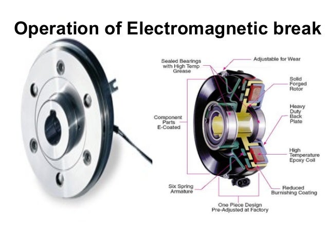
Electromagnetic Clutch:
The electromagnetic type of clutch is operated electrically but the clutch is transmitted mechanically. This clutch has no mechanical linkage to control their engagement which is why fast and smooth operation occurs. It uses a remote for its operation making the clutch to be operated from a distance.
The electrical power is supplied by the battery and the clutch flywheel contains a winding. The winding allows electricity to pass through it produces the electromagnetic field and makes the pressure plate to get engaged. It disengages when its power supply is cut off.
In an electromagnetic clutch, there is a clutch release switch in the gear level which allows the driver to operate the gear lever when changing gears. This switch is operated by cutting off the current supply to the winding which causes the disengagement.
Dog and Spline Clutch:
The dog and spline types of clutches are used to connect the gear and shaft or lock to shaft together. The major parts of the clutch are the dog clutch which contains the external teeth and the sliding sleeve which has the internal teeth. The shafts are designed to rotate one another at the same speed and will never slip. The clutch is said to be engaged when the two shafts are connected. The clutch is disengaged when the sliding sleeve moves back on the splined shaft to have no contact with the driving shaft. These types of clutch are mostly used in manual transmission vehicles which helps to lock different gears.

Vacuum Clutch:
This clutch uses the existing vacuum in the engine manifold for its working. The vacuum clutch consists of a reservoir, non-return valve, vacuum cylinder with piston, and solenoid valve. The reservoir is connected to the inlet manifold through a non-return valve. A vacuum cylinder is connected to a reservoir through a solenoid-operated valve. This solenoid receives power from the battery for its working and the circuit has a switch that is attached to the gear lever. The switch is operated when the driver changes the gear by holding the gear lever.
The solenoid energizes and pulls the valve up which connects one side of the vacuum cylinder and the reservoir. This mechanism opens the passage between the vacuum and the reservoir. Different level of pressure allows the vacuum cylinder piston to move forward and backward. The movement of the piston is transferred to the clutch by a linkage causing it to disengage. If the gear lever is not operated, the switch is open and the clutch remains engaged because of the force of the springs.
Freewheel unit:
The freewheel unit clutch is also known as spring clutch, one-way clutch or overrunning clutch. Its transmission power is in one direction just as bicycle transmission. The freewheel is located behind the gearbox. The main shaft transmits the power from the main shaft to the output shaft which drives the output shaft when the planetary gears are in overdrive.
There is a hub and an outer race contained on the flywheel unit. This hub has internal splines to connect it to the transmission main shaft. The outer surface of the hub has 12 cams designed to hold 12 rollers in a cage between them and the outer race. The outer race is splined to the overdrive outer shaft.
Related Article:
- Slipping clutch: Causes, Symptoms, and how to fix
- Symptoms of a Bad Clutch Fork
- Symptoms of a Failing Clutch Slave Cylinder and its Replacement Cost
- How to Bleed a Hydraulic Clutch
- AC compressor clutch not engaging (causes and how to fix it)
That’s it for this article “Different types of clutch and their working”. I hope the knowledge is attained if so, kindly comment, share, and recommend this website to other technical students. Thanks!
Leave a Reply